 Solar
Thermal Cogeneration
Solar
Thermal Cogeneration[Overview] [Program] [System] [Collector] [Turbine] [Generator] [Controller] [Battery]
Electric Generator
Introduction
An electric generator converts mechanical energy into electrical energy. When an electrical conductor experiences an external magnetic field of changing intensity, the changing magnetic flux induces an emf (1) in the conductor (Faraday's law). The emf drives a current in the conductor that sets up a magnetic field that opposes the change in the flux it sees (Lenz's law, Ampere's law). If the change in flux is the result of motion, conversion from mechanical to electrical energy occurs.
Conventional generators use coils of copper wire for the conductor and magnets to supply the magnetic field. In one configuration, the magnet poles rotate around an axle and the coils are fixed in proximity. When a pole rotates near a coil, its magnetic field penetrates the center (core) of the coil and loops back around. The concentration of flux through the coil core changes with the rotation and induces the emf in the coil (see also inductance, inductor).
The magnetic field setup by the current that is driven by the emf opposes the flux change and so the coil opposes the pole's motion, i.e. the coil repels the approaching pole and attracts the departing pole through Lorentz force. If the coil is open-circuit, the induced emf cannot cause a continuous current/field to oppose the pole's motion. The coil merely instruments with its open-circuit voltage the velocity of the free-spinning pole. But if the coil is close-circuit, it absorbs energy from the pole's momentum and stores it in its field while its current circulates.
The energy stored in the coil is related to its inductance and its current. The coil current depends on the induced emf, the coil inductance and coil and load resistances. The induced emf is related to the flux rate of change seen, i.e. the magnet power and its angular velocity. The resulting coil energy is available for transfer to an electrical load. Energy transfer is related to load resistance. If the load resistance is decreased, then the current flow, the opposition to motion, and the energy transfer are all increased (2).
The dipole nature of magnets is very convenient for creating a constantly changing magnetic field. When a magnet's north and south poles alternately rotate near a fixed coil, the alternating field intensity seen by the coil is sinusoidal, and the field intensity time rate of change and the induced voltage/current are sinusoidal too. The sinusoid is the preferred power waveform because its energy is concentrated in a narrow frequency band to which the generator design may be optimized for efficiency.
(1) Emf, or electromotive force, with units of volts, is actually an energy, not a force.
(2) In an application with a fixed coil resistance and adjustable load resistance, maximum energy transfer with 50% efficiency occurs when the load resistance equals the coil resistance. If coil resistance can be changed, then the lower the coil resistance the better for both energy transfer and efficiency. Coil and load reactances should aways be matched, if possible, to minimize reflection for maximum energy dissipation in the load resistance and minimum dissipation in the coil resistance.
Permanent Magnets and Electromagnets
Magnets are objects that supply magnetic fields useful for mechanical/electrical energy conversion. A simple electric generator consists of a permanent magnet rotating on an axle and a nearby fixed-position coil. Electromagnets may be used in place of permanent magnets in a generator when the cost of permanent magnets is prohibitive. But electromagnets are less efficient because they draw power, they are more bulky, less reliable, and they require commutator brushes on the axle and a priming battery and voltage regulator.
Ferrite (ceramic) is currently the most widespread and cost-effective permanent magnet material. But recent advances have produced permanent magnet materials with very high magnetization. Among the advantages are reduced generator size, reduced rotor mass and reduced centrifugal forces at high speeds. Currently the highest-magnetization material is Neodymium. Its drawbacks include a license fee, brittleness, flammability, and permanent loss of magnetization with heat (170°F-350°F / 20°C-80°C).
Permanent magnets are made by applying a magnetic field to a magnetic material. The strength of the applied field should be high enough to ensure saturation in the material. The material's remanence describes how well it retains its magnetization after the external field is removed. The material's coercivity determines how strong an external field is needed to remove the magnetization. These are sometimes quoted in units of Teslas. These together describe the quality of the resulting permanent magnet. There is also a quality factor sometimes specified in kJ/m^3. Magnetic materials suitable for permanent magnets are referred to as "hard" while those suitable for coil cores are referred to as "soft".
Permanent Magnets
Oersted Technology: About Magnets
Methods of Magnetizing Permanent Magnet (pdf)
Coercivity and Remanence in Permanent Magnets
Multiple Magnets and Coils
Multiple magnets and coils reduce cyclic mechanical stresses by spreading around the axle and balancing the magnetic forces between the rotor and the stator. Odd/staggered phases reduce starting/cogging torque by reducing the number of magnets that are aligned with coils at any rotational angle. Staggered phases also reduce wire thickness/weight needed in transmission and application by 50% or more.
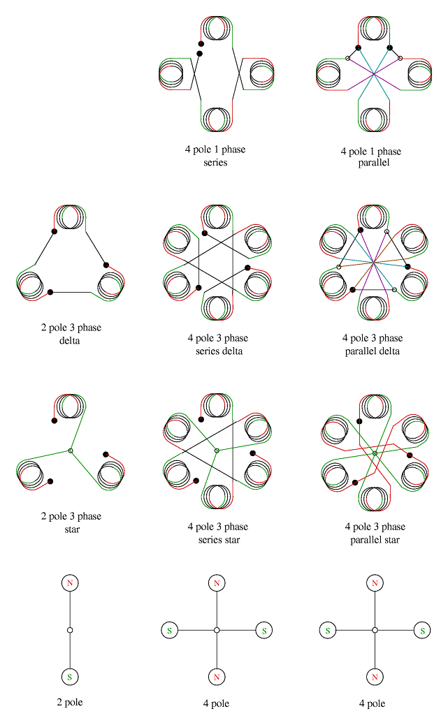
When multiple magnets and coils are placed around an axle it is necessary to alternate the polarity of the magnets so the coils see a continuous change of flux polarity during axle rotation. This requires that the number of magnets be even. In a single phase generator, the number of coils equals the number of magnets (north/south pole pairs) (see figure). Multiple coils around the generator are wired in series or parallel but with alternating polarities consistent with the magnets so that the induced voltages or currents sum together. In a staggered phase generator with N phases and M magnet pole pairs, N groups of M coils are formed by wiring together coils that are offset by M around the generator. N should be odd to minimize starting/cogging torque. Wiring phase group coils in series sums their voltages and wiring in parallel sums their currents.
The N phase groups may be connected in a series loop with the two ends of each phase group comprising one phase tap. The loop should run in a continuous direction around the generator, selecting phase group ends that preserve current direction in the loop. This loop configuration, called delta, gives phase tap current equal to the square root of N times the phase group current. In a different configuration, the N phase groups are terminated together at associated ends consistently spaced in one direction around the generator. Successive phase taps are between successive free group ends spaced similarly around the generator. This configuration, called star, gives phase tap voltage equal to the square root of N times the phase group voltage.
Further characteristics of star and delta are discussed here. In any configuration, connecting wire lengths should provide precise resistance matching for all the coils when measured at the generator terminals. Symmetry is important throughout the generator design.
Dimensions
By Faraday's law, the emf induced in a coil is equal to the number of coil turns times the magnetic flux time rate of change seen. The flux rate of change is the product of the magnet's power and its tangential velocity, which is proportional to the axle rotation rate times the magnet's radius, or distance from the axle center. In the case of sinusoids, the coil current magnitude is related to the emf by the coil inductance, and the load voltage magnitude is calculated from the current magnitude and the coil and load resistances. The output power is the voltage times the current, or the product of the coil turns, magnet power and radius, rotation rate, and load resistance divided by the sum of coil and load resistances.
Practical coils have finite resistance but this should be kept as low as possible to minimize energy loss and maximize efficiency of energy transfer. For a given energy transfer rate, or range thereof, and source and load impedances, the best compromise in coil resistance may be chosen.
The larger the core area, the smaller the core flux density, resistance and heat. Of course, with heat comes power loss and material degradation. The generator circumference should be filled out by coils to maximize power output and by cores to reduce core flux density. The coils' second dimension (either radial or axial) is then extended to approximate the magnet's second dimension. The coil should be long in the dimension perpendicular to the rotation as almost all of the coil's magnetic force interaction with the rotor is concentrated in this dimension. The coils' radius of curvature should be maximum to minimize stress on the insulation.
If available mechanical power comes at low rpm, the generator radius can be increased toward maximum power output until dimensional or stability limits are reached. Then coil and core can extend in the coil's third dimension to fully exploit the power source. Heat from coil electrical resistance limits the number of turns but the wire gauge can be increased to accommodate more turns, limited by the additional flux path length creating more core resistance and heat.
If available mechanical power comes at high rpm, the generator radius can be reduced to minimize centrifugal stress and tangential velocity and associated frequency-dependent electromagnetic losses. The generator axial length can then be extended to fully exploit the power source.
If available mechanical power comes at both high and low rpm then the dimensions may be chosen for the average rpm. This means additional coil/core heat at high rpm and additional magnetic drag at low rpm. Reducing the core density/continuity mitigate both issues simultaneously while additional rotor fanning and mass mitigate them individually.
If the flux through the coil cores is parallel to the axle, the arrangement is called axial flux, and the other arrangement is radial flux. Axial flux can exert axial forces on the bearings and should only be used if the force is to be canceled by other axial forces. See Axial Loads.
Wire Gauge
In light of the above, to achieve maximum power transfer while minimizing space and materials, a smaller wire gauge is used to enable more coil turns and thus deliver more power in the same space. But wire resistance, even with copper, can create significant heat in longer lengths of smaller gauge wire, wasting energy and stressing materials. (see magnet wire)
If the load resistance is high during maximum sustained power transfer then high voltage is needed to transmit available power and the coil turns should be greater, the wire gauge smaller and the coil insulation strong to withstand the high voltage. If the load resistance is low during maximum sustained power transfer then high current is needed to transmit available power and the coil turns should be fewer and the wire gauge larger to withstand the high current.
If the time rate of flux change is high then the wire gauge should be small to minimize the skin effect. But if the load resistance is low, more coils with fewer turns may be configured in parallel to better match the load resistance for maximum power transfer.
Wire Gauge Table
Magnet Wire and Coil Winding
Magnet wire is usually made from copper with a coating of enamel insulation. The insulation is vulnerable to various stresses and contaminations which deteriorate the insulation and lead to eventual coil failure. Commercial priority has been on compact coil size which may compromise insulation thickness and longevity of the coils. To maximize the longevity of the coils, the most reputable wire vendor should be found and the highest thermal classes and insulation builds should be considered.
The energy transfer in the generator involves a force between the rotating magnets and the coil wires. This force is a sinusoidal push/pull in the direction of rotation on the wire lengths that are perpendicular to the rotation. The spacing and tension of coil winding should be consistent to prevent concentrated areas of stress in the coil from this force. The coil should be supported on the two appropriate sides by the core that surrounds it and epoxy potting may be the best way to ensure the coils maintain rigid support.
The coils should be carefully wound to ensure consistent winding tension, minimizing both vibrations and premature insulation failure. Winding should take place in a dust and humidity-free environment. Winding tension specifications should be heeded. Avoid touching or otherwise contaminating the wire.
Dust, dirt, metal filings, oils, humidity and external vibration, heat and light decrease heat dissipation and/or react with or stress the enamel and contribute to insulation deterioration. Options for mitigating these include potting coils in epoxy or varnish. Potting also reduces induction of high frequency harmonics produced by individual windings of smaller gauge wire prone to independent vibration. Potting also supports the coils against the forces exerted by the magnets.
Femco Magnet Wire
Coil Cores
Iron and other ferrous materials have very high magnetic permeability, which allows their magnetization by external fields to add greatly to those fields. To maximize magnetic induction in the coils, iron cores may be built up through and around the coils and magnets, to form a dense magnetic flux circuit when a magnet and coil align through rotation.
But iron conducts electricity so eddy currents are induced in the core perpendicular to the magnetic flux. Iron's relatively high electrical resistance converts a lot of this current into heat. The heat draws energy directly but also by decreasing the iron's magnetic permeability, e.g., 25% loss from 20°C to 80°C. So it is necessary to slice the core up into thin laminates, electrically isolated from each other by a coat of lacquer. Higher rates of magnetic flux change (higher rotor frequency) produce smaller eddy paths so then it becomes necessary to reduce the laminate thickness or consider tape-wound cores, or powdered iron cores in which dielectric between the iron granules provides gaps that block the smaller eddy current loops. Increasing the core area can reduce eddy currents by reducing the flux density but mechanical issues usually limit this approach.
Further heat is produced in the core as the core molecules resist changes in their magnetization. This resistance to change, known as magnetic hysteresis, is greatly reduced by mixing of silicon in the iron and annealing it.
The core would ideally extend the entire loop between the magnet pole, through the coil and back around to the magnet's opposite pole except for the gaps that allow the magnet to rotate. The smaller the gaps the greater the magnetic flux density but other parameters may be increased to compensate for larger gaps that allow for magnetic balancing adjustments on the rotor. If power volume density (compact size) isn't a priority the loop may have further discontinuities that simplify fabrication with power requirements being met by other means. The optimum sum total gap in a core loop aligns the core's magnetic saturation point with the generator's maximum rated speed.
Mechanical & Thermal
The generator mechanics must be rigid and moving parts balanced to minimize vibration. Vibration wastes energy and produces excess heat, wear and noise, reducing the efficiency and life of components, especially the coils and bearings. The materials must be chosen to withstand thermal and mechanical stress to maintain rigidity and balance. The axle should be carefully machined/balanced, the magnet assembly (rotor) should be securely attached and the rotor/axle assembly carefully balanced.
For high speeds the magnets must be tightly secured against centrifugal (outward radial) force. For high power, the magnets as well as the coils and cores must be tightly secured in the magnetic flux direction (radial or axial) and tangentially. Most magnets are too brittle to be bolted and must be glued with strong epoxy. Care should also be taken to ensure electromagnetic balance with consistency among the magnets and coils, in materials, construction and position. The coil assembly should have 3 dimensional setscrew adjustment to secure it at the composite mechanical/magnetic equilibrium position at the most prevalent operating conditions.
For high speeds the rotor surfaces should be continuous and smooth to minimize windage loss. This can be accomplished with epoxy filler around the magnets, mixing other non-magnetic materials to reduce the quantity of epoxy. If running at high speed the axle bearings must be well chosen, aligned and lubricated. When magnets/coils face radially, most bearing force is radial. When magnets/coils face axially, bearing forces are both axial and radial. See Axial Loads.
Excess heat may be created by ambient conditions, electrical resistance in the coils and cores, eddy currents in the cores, and vibration. Excess heat weakens the insulation on the coil wire and core laminates, and with vibration, causes it to shed and the coil to weaken or fail. More on magnet wire. Excess heat prematurely breaks down bearing lubricant and thus bearings too. Heat adversely affects the power of magnets. Internal heat should be minimized by design but can be mitigated by rotor-induced air turbulence.
The bearings and lubricant must remain cool and clean. Excess volume or density of lubricant can create excess load and heat. Proper seals are very important for keeping out contaminants because contamination is a leading cause of premature bearing failure. To maximize the generator life, inspect and replace seals, bearings and lubricant in a timely fashion and avoid contamination. More on bearings.
Motor Temperature Ratings
Axial Loads
In an axial flux configuration, the interaction between the magnets and the coils/cores presents axial loads on the magnet rotor, coil stator and the bearings. The interaction varies with the electrical load. To cancel the axial loads, either a pair of rotors on either side of the stator, or a pair of stators on either side of the rotor will suffice.
If the turbine is on the same shaft (highly preferable) then its steam ejection might also present an axial load on the bearings, depending mostly on the outlet design. Even if the outlet cancels the axial load this may vary with the fluid throughput. The average load may be canceled by making the generator stator-rotor gap on one side wider than the other. This will reduce the generator's power compared to minimizing both gaps. But this is a legitimate trade-off because the additional materials required to make up the difference will be paid for easily in savings to the bearings. Another option is to use the stator pair configuration while having the power electronics vary the electrical loads on the two stators to maintain the axial load balance as the speed changes.
Construction
Forms should be made that enable consistent tension and spacing of coil wire during winding. The wire should remain as clean as possible, no touching, no excess humidity or temperature extremes, no dust/dirt.
Cogging Torque
Cogging torque is created by the magnetic attraction between the magnets and coil cores of a motor/generator. These disruptions to the smooth rotor motion can make the motor/generator difficult to start and run at low speeds. At higher speed, the rotor momentum overcomes the cogging torque. The coils tend to cancel the cogging torque during rotation by presenting an opposing torque. For easiest startup, cogging torque may be reduced by an odd/staggered-phase design. This divides the total power between the phase groups and limits the number of groups aligned with magnets at any time to one. Cogging torque might be further reduced by up to 50% by arching the magnet surface facing the coil.
Permanent Magnet Motor
The permanent magnet (PM) AC generator becomes a PM AC motor, or synchronous motor, when power sinusoids are applied to its electrical terminals. This duality is utilized in electric vehicle drive motors/regenerative brakes.
Most AC motors are induction motors, with coil stators and squirrel-cage rotors. These rotors consist of heavy conductors and laminates. A magnetic field is setup in the rotor by induction from the stator. The induction motor suffers significant losses in creating the rotor magnetic field compared to the PM rotor, which utilizes the potential energy in permanent magnets. Typical efficiency of an induction motor is 86%. Typical efficiency of a synchronous motor is 93%.
Synchronous and induction AC motors are brushless and therefore more reliable/efficient than DC motors and universal motors. This is due to non-linear power waveforms created by brushed commutators, which also produce ozone and noise, but allow a lighter, more compact motor.
The synchronous motor is commonly used in servo applications and is usually driven by a solid-state variable frequency drive (VFD) that enables dynamic control over the motor's torque and speed, allowing smooth starts/stops that can greatly extend the life of components.
Many synchronous motors/drives use an rpm sensor to maintain speed under changing loads, but sensor reliability can be an issue. Another approach is to sense the phase of the back-emf from the motor. When the load changes, the speed changes and back-emf phase changes with it. Sensing the phase change allows the control system to correct the speed or optimize the speed/voltage as the load changes. A similar approach is Direct Torque Control.
It may seem that the power supply must work against the motor's back-emf. But back-emf draws no power because there is no associated current. The back-emf simply changes the reference for the applied forward voltage. The current draw is derived from the voltage difference and the circuit resistance.
Most large AC motors are three-phase. Multi-phase motors are self-starting, quieter and more efficient. Most small AC motors are single-phase mainly due to relatively high wiring/connector costs. Odd/staggered phase provides similar benefits to both motors and generators. For efficiency and reduced stress, the power drive should be well-balanced electrically and the motor balanced thermally, magnetically, electrically and mechanically.
Permanent Magnet Synchronous Motor
Appliance motors turn green
References
All About Circuits: Volume II - AC
Three-phase power systems
Motor Maintenance
Coil Winding Options
Updated: FILEDATE
Copyright (c) 2005, 2009 Robert Drury
Permission is granted to copy, distribute and/or modify this document
under the terms of the GNU Free Documentation License, Version 1.2
or any later version published by the Free Software Foundation;
with no Invariant Sections, no Front-Cover Texts, and no Back-Cover Texts.
See "GNU Free Documentation License".
Disclaimer: This information may contain inaccuracies and is provided
without warranty. Safety first when working with high temperatures,
pressures, potentials, speeds, energies, various tools and materials.